

Quick Study of Bring Your Own Vulnerable Driver (BYOVD)
Quick Study of BYOVD including Root Cause Analysis and how it can be abused by attackers to disable or evade security solutions.
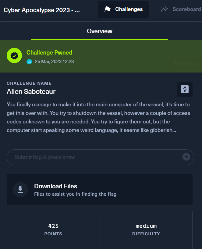
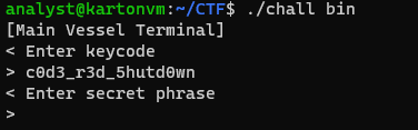
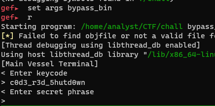
This challenge is a Virtual Machine (VM) based reversing challenge from Hack The Box CTF, Cyber Apocalypse 2023. This challenge requires participants to reverse engineer a simple custom instruction sets. In this challenge, the objective was to gain access to the main computer and shutdown the vessel. But to do so, access codes are required which is incidentally the flag for the challenge. The following image shows the description of the challenge. For this writeup, it is assumed that the reader has done some reversing on this binary. Therefore, this would include the important pointers and the script for solving the challenge.
To gain access to the main computer of the vessel in the Shutdown Sequence challenge, the keycode and secret code has to be supplied. To begin, two files were downloaded. One is the main binary which takes in an argument for a ROM like file which is responsible for running the custom virtual machine implemented in the challenge. Additionally, the gibberish, weird language described in the description refers to encrypted instructions which can be decrypted via a single byte XOR.
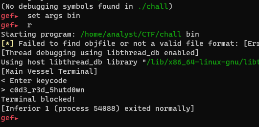
Interestingly, the challenge incorporated an anti-debugging feature that attempted to detect when a debugger like GDB was attached via the ptrace syscall. For this challenge, I have written a minimal disassembler that emits pseudo assembly to aid in the reversing process.
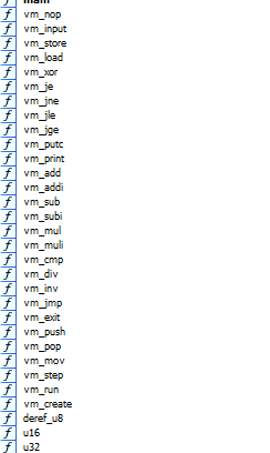
The challenge in a nutshell consists of common and familiar instructions. They are
The following describes the VM in a high-level overview.
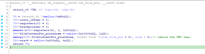
A VM Context is created via vm_create which contains:
a. Registers
b. Stack
c. Stack Pointer
d. Program Counter
vm_step in a while loop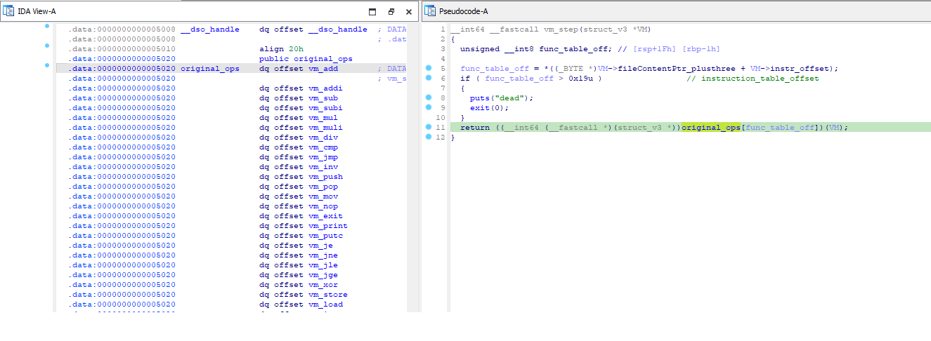
b. Instruction opcode ranges from 0x00 to 0x19
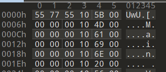
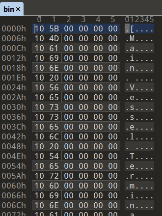
b. Example 1 : {10 4D 00 00 00 00}
i. Opcode 0x10 maps to `vm_putc` which prints a character in the console. The next byte indicates the ASCII character `M` to print out.
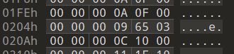
c. Example 2 : {0A 0f 00 00 00 00}
i. Opcode 0x0A maps to `vm_push`. The next byte refers to the register whose value would be pushed onto the stack.
To make it easier to analyze and reverse engineer, the first three bytes from the bin file was removed completely. The view of six bytes per row in the hex editor was set to make it easier to view the instructions.
Familiarizing myself with the layouts and pattern in the decompiled code is definitely useful when writing the disassembler. The following few examples shows how the disassemblies were emited.
vm_pushstruct_v3 *__fastcall vm_push(struct_v3 *a1)
{
struct_v3 *result; // rax
*(4LL * a1->stackpointer++ + a1->stack) = *&a1->registers[4
* deref_u8(a1->fileContentPtr_plusthree + a1->instr_offset + 1)
+ 4];
result = a1;
a1->instr_offset += 6;
return result;
}
This instruction pushes a byte onto the stack from the register pointed to by the second byte in the instruction.
The following shows an example disassembly for this instruction.
vm_jestruct_v3 *__fastcall vm_je(struct_v3 *a1)
{
int v1; // edx
struct_v3 *result; // rax
int v3; // [rsp+18h] [rbp-8h]
v3 = *&a1->registers[4 * deref_u8(a1->fileContentPtr_plusthree + a1->instr_offset + 1) + 4];
if ( v3 == *&a1->registers[4 * deref_u8(a1->fileContentPtr_plusthree + a1->instr_offset + 2) + 4] )
{
v1 = 6 * u16(a1->fileContentPtr_plusthree + a1->instr_offset + 3);
result = a1;
a1->instr_offset = v1;
}
else
{
result = a1;
a1->instr_offset += 6;
}
return result;
}
The value of register pointed to by second byte of the instruction is checked against the value register pointed to by the third byte. If the values are equal, then the instr_offset or the instruction pointer is modified. Else, it would move to the next instruction.
The following shows the code used for the disassembler to disassemble the vm_je operation in the VM.

The output is as follows:

vm_inv (Anti-Debugging)vm_inv refers to the INVocation of syscalls. The syscall number comes from the second byte of the instruction.
struct_v3 *__fastcall vm_inv(struct_v3 *a1)
{
…
…
  sysno = deref_u8(a1->fileContentPtr_plusthree + a1->instr_offset + 1);
  v1 = deref_u8(a1->fileContentPtr_plusthree + a1->instr_offset + 2);
  sysno_4 = v1;
  if ( v1 )
  {
    stack = a1->stack;
    v3 = a1->stackpointer - 1;
    a1->stackpointer = v3;
    v4 = *(stack + 4LL * v3);
  }
  else
  {
    v4 = 0;
  }
  file_descriptor = v4;
  if ( sysno_4 <= 1 )
  {
    v7 = 0;
  }
  else
  {
    v5 = a1->stack;
    v6 = a1->stackpointer - 1;
    a1->stackpointer = v6;
    v7 = *(v5 + 4LL * v6);
  }
  v15 = v7;
  if ( sysno_4 <= 2 )
  {
    v10 = 0;
  }
  else
  {
    v8 = a1->stack;
    v9 = a1->stackpointer - 1;
    a1->stackpointer = v9;
    v10 = *(v8 + 4LL * v9);
  }
  *&a1->registers[128] = syscall(sysno, file_descriptor, v15, v10);
  result = a1;
  a1->instr_offset += 6;
  return result;
}
The following shows the code used for emiting the disassembly for the syscall invoke function.

And finally, the example output from the bin file:

The result of the syscall is stored in REG:[0x1f] which corresponds to ` *&a1->registers[0x80]`. You can find the code of the disassembler in the appendix section at the end of this blog.
This section covers the analysis after the initial disassembly.
The following is the dumped disassembly of the keycode checking function
0x0     :vm_putc        [
…
<prints banner message>
…
0xf0    :vm_putc        >
0xf6    :vm_putc
0xfc    :vm_mov         REG[0x1e]  =  0 f a0
0x102   :vm_mov         REG[0x1c]  =  0 0 0
0x108   :vm_mov         REG[0x1d]  =  0 0 11
0x10e   :vm_input       input to REG[0x19]
0x114   :vm_store       bin[REG[0x1e]] = REG[0x19]
0x11a   :vm_addi        REG[0x1e] = REG[0x1e] + 0x1
0x120   :vm_addi        REG[0x1c] = REG[0x1c] + 0x1
0x126   :vm_jle         if REG[0x1c] <= REG[0x1d] then JMP bin[0x10e]
0x12c   :vm_mov         REG[0x1e]  =  0 10 4
0x132   :vm_mov         REG[0x1f]  =  0 f a0
0x138   :vm_mov         REG[0x1c]  =  0 0 0
0x13e   :vm_mov         REG[0x1d]  =  0 0 a
0x144   :vm_mov         REG[0x1b]  =  0 0 a9
0x14a   :vm_mov         REG[0x17]  =  0 0 0
0x150   :vm_load        REG[0x19] = bin[REG[0x1e]]
0x156   :vm_load        REG[0x18] = bin[REG[0x1f]]
0x15c   :vm_xor         REG:[0x19] = REG:[0x1b] ^ REG:[0x19]
0x162   :vm_je  IF REG:[0x19] == REG:[0x18] THEN JMP TO 0x1d4
0x168   :vm_putc        U
0x16e   :vm_putc        n
0x174   :vm_putc        k
0x17a   :vm_putc        n
0x180   :vm_putc        o
0x186   :vm_putc        w
0x18c   :vm_putc        n
0x192   :vm_putc
0x198   :vm_putc        k
0x19e   :vm_putc        e
0x1a4   :vm_putc        y
0x1aa   :vm_putc        c
0x1b0   :vm_putc        o
0x1b6   :vm_putc        d
0x1bc   :vm_putc        e
0x1c2   :vm_putc        !
0x1c8   :vm_putc
0x1ce   :vm_exit
0x1d4   :vm_addi        REG[0x1e] = REG[0x1e] + 0x1
0x1da   :vm_addi        REG[0x1f] = REG[0x1f] + 0x1
0x1e0   :vm_addi        REG[0x1c] = REG[0x1c] + 0x1
0x1e6   :vm_jle         if REG[0x1c] <= REG[0x1d] then JMP bin[0x150]
The key code ` c0d3_r3d_5hutd0wn` is retrieved via a simple script.
Entering the key should bring us to the next stage. This is peculiar at first due to the absence of vm_putc instructions putting the Enter secret phrase string in the disassembled code.
It should be noted that the output above is possible when a debugger is not attached to the process. This is what it would look like when GDB is attached to the process.
PTRACEThis instruction is used to invoke the ptrace syscall number 0x65. This instruction is used only once in the entire bin file. This value is then used to compare to see if a debugger is present when debugging.
Fortunately, patching of the bin file is sufficient:
vm_je (0x11) to vm_jne(0x12)vm_nop
b. We can also replace the three push statements as wellf = open("./bin","rb")
bindata = bytearray(f.read())
f.close()
bindata[0x213] = 0x12 # Change JE to JNE
f = open("./bypass_bin","wb")
f.write(bindata)
f.close()
The newly disassembled code demonstrating the successful patch.
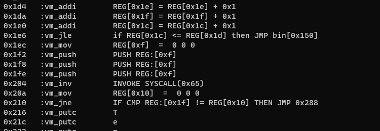
The patched bin file should successfully bypass the anti-debugging feature.
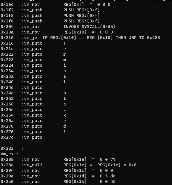
While it may be tempting to conclude the end of the challenge with the keycode, the second stage is present to bring us back from our dream. The following disassembly explains that there are more code.
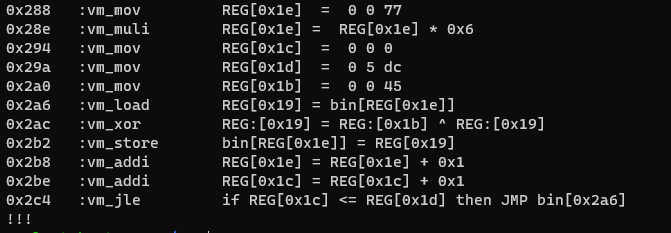
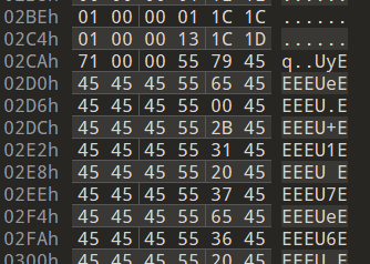
The reason that the rest of the instructions are not present is due to the encrypted instructions containing opcode values larger than 0x19. To get the rest of the disassembly, we have to decrypt the values in the bin file.
# Assumes that the bin file contains the three ignored bytes

```python
f = open("./bypass_bin","rb")
bindata = bytearray(f.read())
f.close()
for i in range(len(bindata[0x2ca+3 : 0x591])):
    bindata[0x2ca+3+i] ^= 0x45
f = open("./decrypted_bin","wb")
f.write(bindata)
f.close()
history
With the instructions properly decrypted, the prompt to enter secret phrase can be found.
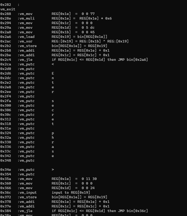
With this, further light can be shed on what algorithms is used to manipulate the secret phrase before comparing to a result bytearray.
This part will explain how the pass phrase input by user is manipulated and the operations can be reversed to retrieve the flag.
The algorithm that was employed is not complicated.
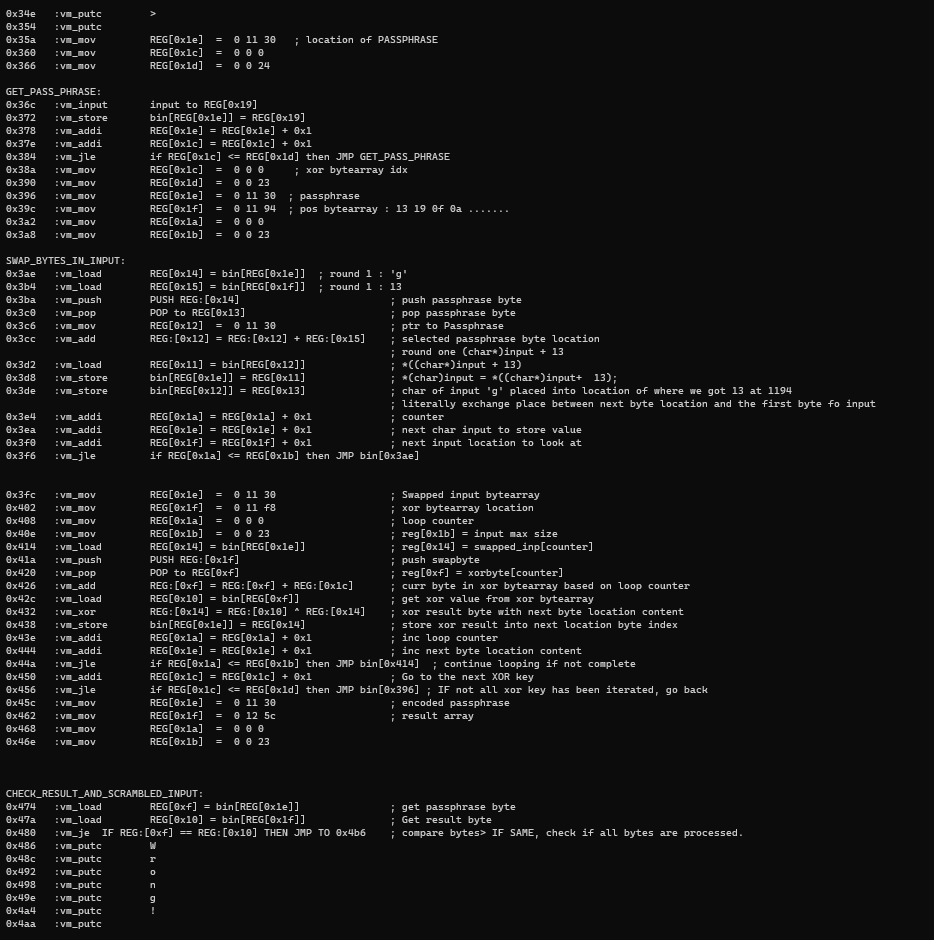
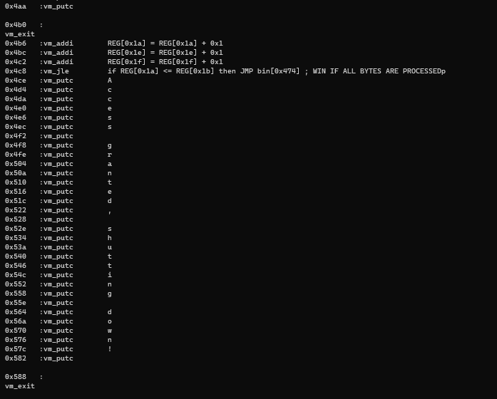
The following presents the pseudocode of the algorithm for sanity
# Enter 0x24 bytes
passphrase = bytearray(input("Enter secret phrase :"))

for j in range(len(xor_list)):

    # Swap position
    for i in range(len(pos_list)):
        swap_position  = pos_list[i]
        passphrase[i], passphrase[swap_position]  = passphrase[swap_position], passphrase[i]

    # Xor with key after swapping
    xor_key = xor_list[j]
    for k in range(len(passphrase)):
        passphrase[k] ^= xor_key
The plan is simple.
f = open("bypass_bin","rb")
bindata = f.read()
f.close()
pos = bytearray(bindata[0x1194+3:0x11b8+3])
xor_list = bytearray(bindata[0x11f8+3:0x121c+3])
result_list = bytearray(bindata[0x125c+3:0x1280+3])
firstpart = bytearray(bindata[0x1004+3:0x1004+18+2])
for i in range(len(firstpart)):
firstpart[i] ^= 0xa9
print("KeyCode : ", firstpart)
def restore(swapped_data, pos):
for i in range(len(pos)-1, -1, -1):
swapped_data[pos[i]], swapped_data[i] = swapped_data[i], swapped_data[pos[i]]
return swapped_data
def solve(result_list, xor_list):
for i in range(len(xor_list)):
xor_key= xor_list[i]
for j in range(len(result_list)):
curr_byte = result_list[j]
result_list[j] ^= xor_key
result_list = restore(result_list,pos)
print(result_list)
solve(result_list,xor_list)
"""
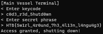
KeyCode : bytearray(b'c0d3_r3d_5hutd0wn')
bytearray(b'HTB{5w1rl_4r0und_7h3_4l13n_l4ngu4g3}')
"""
import sys

s = """
0000000000005020 original_ops    dq offset vm_add
.data:0000000000005020                 dq offset vm_addi
.data:0000000000005020                 dq offset vm_sub
.data:0000000000005020                 dq offset vm_subi
.data:0000000000005020                 dq offset vm_mul
.data:0000000000005020                 dq offset vm_muli
.data:0000000000005020                 dq offset vm_div
.data:0000000000005020                 dq offset vm_cmp
.data:0000000000005020                 dq offset vm_jmp
.data:0000000000005020                 dq offset vm_inv
.data:0000000000005020                 dq offset vm_push
.data:0000000000005020                 dq offset vm_pop
.data:0000000000005020                 dq offset vm_mov
.data:0000000000005020                 dq offset vm_nop
.data:0000000000005020                 dq offset vm_exit
.data:0000000000005020                 dq offset vm_print
.data:0000000000005020                 dq offset vm_putc
.data:0000000000005020                 dq offset vm_je
.data:0000000000005020                 dq offset vm_jne
.data:0000000000005020                 dq offset vm_jle
.data:0000000000005020                 dq offset vm_jge
.data:0000000000005020                 dq offset vm_xor
.data:0000000000005020                 dq offset vm_store
.data:0000000000005020                 dq offset vm_load
.data:0000000000005020                 dq offset vm_input"""

instruction_offsets = []

for i in s.split("\n")[1:]:
    temp = ""
    if "offset" in i:
        temp = i.split("offset")[1]
    instruction_offsets.append(temp)

def read_bin(fname):
    f = open(fname,"rb")
    bin_data = f.read()[3:]
    f.close()
    return bin_data

function_set = set()
function_set.add("vm_putc")

#  First three UwU is not needed
#data = read_bin("./bin")[3:]
#data = read_bin("./bypass_bin")
data = read_bin("./decrypted_bin")
#data = read_bin("./deob_instr")[3:]
#data = read_bin("./new_patch_bin")[3:]

for i in range(0,len(data),6):
    if data[i] >0x19:
        break
    fn_name = instruction_offsets[data[i]].strip()
    function_set.add(fn_name)

for i in range(0,len(data),6):

    if data[i] > 0x19:
        break
    sys.stdout.write("\n" +hex(i) + "\t:")

    fn_name = instruction_offsets[data[i]].strip()
    second_instr_byte = data[i+1]
    third_instr_byte = data[i+2]
    fourth_instr_byte = data[i+3]
    fifth_instr_byte = data[i+4]
    if fn_name == "vm_putc":
        sys.stdout.write(fn_name + " \t" +chr(second_instr_byte ))
    elif fn_name == "vm_mov":
        src = hex(fifth_instr_byte)[2:]+" " + hex(fourth_instr_byte)[2:]+" " + hex(third_instr_byte)[2:]
        dest = second_instr_byte
        sys.stdout.write(fn_name + " \tREG[" + hex(dest) + "]  =  " + src)
    elif fn_name == "vm_input":
        location_to_store_byte= second_instr_byte
        sys.stdout.write(fn_name + " \tinput to REG[" + hex(location_to_store_byte) + "]")
    elif fn_name == "vm_store":
        offset =  second_instr_byte
        data_to_store = third_instr_byte
        sys.stdout.write(fn_name + " \tbin[REG[" +  hex(offset) + "]] = REG[" +  hex(data_to_store) + "]")
    elif fn_name == "vm_addi":
        result = second_instr_byte
        reg = third_instr_byte
        imm = fourth_instr_byte
        sys.stdout.write(fn_name + " \tREG["+hex(result) + "] = REG["+ hex(reg) + "] + " + hex(imm) )
    elif fn_name == "vm_jle":
        left = second_instr_byte
        right = third_instr_byte
        jump_location = hex(int(hex(fifth_instr_byte)[2:] +  hex(fourth_instr_byte)[2:] , 16)*6)
        sys.stdout.write(fn_name + " \tif REG[" + hex(left) + "] <= REG[" + hex(right) + "] then JMP bin[" + jump_location + "]")
    elif fn_name == "vm_muli":
        reg = third_instr_byte
        imm = fourth_instr_byte
        dest = second_instr_byte
        sys.stdout.write(fn_name + " \tREG[" + hex(dest) + "] =  REG[" + hex(reg) + "] * " + hex(imm))
    elif fn_name == "vm_exit":
        sys.stdout.write("\n" + fn_name)
    elif fn_name == "vm_load":
        dest = second_instr_byte
        data_to_load = third_instr_byte
        sys.stdout.write(fn_name +  " \tREG[" + hex(dest)  + "] = bin[" + "REG["+ hex(data_to_load)+ "]] ")
    elif fn_name == "vm_xor":
        right = third_instr_byte
        left = fourth_instr_byte
        result = second_instr_byte
        sys.stdout.write(fn_name  + " \tREG:["+hex(result)+"] = REG:["+hex(left) + "] ^ REG:["+hex(right)+"]")
    elif fn_name == "vm_push":
        data_to_push = second_instr_byte
        sys.stdout.write(fn_name + " \tPUSH REG:["+hex(data_to_push)+  "]")
    elif fn_name == "vm_inv":
        sysno = second_instr_byte
        sys.stdout.write(fn_name + " \tINVOKE SYSCALL(" + hex(sysno) +     ")")
    elif fn_name == "vm_je":
        left = second_instr_byte
        right = third_instr_byte
        jump_location = hex(int(hex(fifth_instr_byte)[2:] +  hex(fourth_instr_byte)[2:] , 16)*6)
        sys.stdout.write(fn_name + " \tIF REG:[" + hex(left)  + "] == REG:[" + hex(right) + "] THEN JMP TO "+ jump_location)
    elif fn_name == "vm_pop":
        popped_data = second_instr_byte
        sys.stdout.write(fn_name + " \tPOP to REG["+hex(popped_data) + "]")
    elif fn_name == "vm_print":
        to_print = second_instr_byte
        sys.stdout.write(fn_name + " \tPRINT REG["+hex(to_print) + "]")
    elif fn_name == "vm_jne":
        first = second_instr_byte
        second = third_instr_byte
        jump_location = hex(int(hex(fifth_instr_byte)[2:] +  hex(fourth_instr_byte)[2:] , 16)*6)
        sys.stdout.write(fn_name + " \tIF CMP REG:["+hex(first) + "] != REG["+hex(second) + "] THEN JMP " + jump_location)
    elif fn_name == "vm_add":
        left = third_instr_byte
        right = fourth_instr_byte
        result = second_instr_byte
        sys.stdout.write(fn_name + " \tREG:["+hex(result) + "] = REG:["+hex(left) + "] + REG:[" + hex(right) + "] ")
    elif fn_name == "vm_nop":
        sys.stdout.write(fn_name)
    else:
        sys.stdout.write(fn_name + " : not implemented ")
        continue
    if fn_name in function_set:
        function_set.remove(fn_name)

print()

print("!!!")
for i in function_set:
    print(i)
0x0     :vm_putc        [
0x6     :vm_putc        M
0xc     :vm_putc        a
0x12    :vm_putc        i
0x18    :vm_putc        n
0x1e    :vm_putc
0x24    :vm_putc        V
0x2a    :vm_putc        e
0x30    :vm_putc        s
0x36    :vm_putc        s
0x3c    :vm_putc        e
0x42    :vm_putc        l
0x48    :vm_putc
0x4e    :vm_putc        T
0x54    :vm_putc        e
0x5a    :vm_putc        r
0x60    :vm_putc        m
0x66    :vm_putc        i
0x6c    :vm_putc        n
0x72    :vm_putc        a
0x78    :vm_putc        l
0x7e    :vm_putc        ]
0x84    :vm_putc

0x8a    :vm_putc        <
0x90    :vm_putc
0x96    :vm_putc        E
0x9c    :vm_putc        n
0xa2    :vm_putc        t
0xa8    :vm_putc        e
0xae    :vm_putc        r
0xb4    :vm_putc
0xba    :vm_putc        k
0xc0    :vm_putc        e
0xc6    :vm_putc        y
0xcc    :vm_putc        c
0xd2    :vm_putc        o
0xd8    :vm_putc        d
0xde    :vm_putc        e
0xe4    :vm_putc
0xea    :vm_putc

0xf0    :vm_putc        >
0xf6    :vm_putc
0xfc    :vm_mov         REG[0x1e]  =  0 f a0
0x102   :vm_mov         REG[0x1c]  =  0 0 0
0x108   :vm_mov         REG[0x1d]  =  0 0 11
0x10e   :vm_input       input to REG[0x19]                      ; Store user input
0x114   :vm_store       bin[REG[0x1e]] = REG[0x19]              ; store into location 0xFA0
0x11a   :vm_addi        REG[0x1e] = REG[0x1e] + 0x1
0x120   :vm_addi        REG[0x1c] = REG[0x1c] + 0x1
0x126   :vm_jle         if REG[0x1c] <= REG[0x1d] then JMP bin[0x10e]
0x12c   :vm_mov         REG[0x1e]  =  0 10 4
0x132   :vm_mov         REG[0x1f]  =  0 f a0                    ; Location of user input
0x138   :vm_mov         REG[0x1c]  =  0 0 0
0x13e   :vm_mov         REG[0x1d]  =  0 0 a
0x144   :vm_mov         REG[0x1b]  =  0 0 a9
0x14a   :vm_mov         REG[0x17]  =  0 0 0
0x150   :vm_load        REG[0x19] = bin[REG[0x1e]]              ; 0x19 contain bytes in memroy
0x156   :vm_load        REG[0x18] = bin[REG[0x1f]]              ; pointer to userinput
0x15c   :vm_xor         REG:[0x19] = REG:[0x1b] ^ REG:[0x19]    ; 0xa9 & memory
0x162   :vm_jne         IF CMP REG:[0x19] != REG[0x18] THEN JMP 0x1d4  ; compare if they are the same
0x168   :vm_putc        U
0x16e   :vm_putc        n
0x174   :vm_putc        k
0x17a   :vm_putc        n
0x180   :vm_putc        o
0x186   :vm_putc        w
0x18c   :vm_putc        n
0x192   :vm_putc
0x198   :vm_putc        k
0x19e   :vm_putc        e
0x1a4   :vm_putc        y
0x1aa   :vm_putc        c
0x1b0   :vm_putc        o
0x1b6   :vm_putc        d
0x1bc   :vm_putc        e
0x1c2   :vm_putc        !
0x1c8   :vm_putc

0x1ce   :
vm_exit
0x1d4   :vm_addi        REG[0x1e] = REG[0x1e] + 0x1
0x1da   :vm_addi        REG[0x1f] = REG[0x1f] + 0x1
0x1e0   :vm_addi        REG[0x1c] = REG[0x1c] + 0x1
0x1e6   :vm_jle         if REG[0x1c] <= REG[0x1d] then JMP bin[0x150]
0x1ec   :vm_mov         REG[0xf]  =  0 0 0
0x1f2   :vm_nop
0x1f8   :vm_nop
0x1fe   :vm_nop
0x204   :vm_nop
0x20a   :vm_mov         REG[0x10]  =  0 0 0
0x210   :vm_jne         IF CMP REG:[0x1f] != REG[0x10] THEN JMP 0x288
0x216   :vm_putc        T
0x21c   :vm_putc        e
0x222   :vm_putc        r
0x228   :vm_putc        m
0x22e   :vm_putc        i
0x234   :vm_putc        n
0x23a   :vm_putc        a
0x240   :vm_putc        l
0x246   :vm_putc
0x24c   :vm_putc        b
0x252   :vm_putc        l
0x258   :vm_putc        o
0x25e   :vm_putc        c
0x264   :vm_putc        k
0x26a   :vm_putc        e
0x270   :vm_putc        d
0x276   :vm_putc        !
0x27c   :vm_putc

0x282   :
vm_exit
0x288   :vm_mov         REG[0x1e]  =  0 0 77
0x28e   :vm_muli        REG[0x1e] =  REG[0x1e] * 0x6
0x294   :vm_mov         REG[0x1c]  =  0 0 0
0x29a   :vm_mov         REG[0x1d]  =  0 5 dc
0x2a0   :vm_mov         REG[0x1b]  =  0 0 45
0x2a6   :vm_load        REG[0x19] = bin[REG[0x1e]]
0x2ac   :vm_nop
0x2b2   :vm_store       bin[REG[0x1e]] = REG[0x19]
0x2b8   :vm_addi        REG[0x1e] = REG[0x1e] + 0x1
0x2be   :vm_addi        REG[0x1c] = REG[0x1c] + 0x1
0x2c4   :vm_jle         if REG[0x1c] <= REG[0x1d] then JMP bin[0x2a6]
0x2ca   :vm_putc        <
0x2d0   :vm_putc
0x2d6   :vm_putc        E
0x2dc   :vm_putc        n
0x2e2   :vm_putc        t
0x2e8   :vm_putc        e
0x2ee   :vm_putc        r
0x2f4   :vm_putc
0x2fa   :vm_putc        s
0x300   :vm_putc        e
0x306   :vm_putc        c
0x30c   :vm_putc        r
0x312   :vm_putc        e
0x318   :vm_putc        t
0x31e   :vm_putc
0x324   :vm_putc        p
0x32a   :vm_putc        h
0x330   :vm_putc        r
0x336   :vm_putc        a
0x33c   :vm_putc        s
0x342   :vm_putc        e
0x348   :vm_putc

0x34e   :vm_putc        >
0x354   :vm_putc
0x35a   :vm_mov         REG[0x1e]  =  0 11 30   ; location of PASSPHRASE
0x360   :vm_mov         REG[0x1c]  =  0 0 0
0x366   :vm_mov         REG[0x1d]  =  0 0 24

GET_PASS_PHRASE:
0x36c   :vm_input       input to REG[0x19]
0x372   :vm_store       bin[REG[0x1e]] = REG[0x19]
0x378   :vm_addi        REG[0x1e] = REG[0x1e] + 0x1
0x37e   :vm_addi        REG[0x1c] = REG[0x1c] + 0x1
0x384   :vm_jle         if REG[0x1c] <= REG[0x1d] then JMP GET_PASS_PHRASE
0x38a   :vm_mov         REG[0x1c]  =  0 0 0     ; xor bytearray idx
0x390   :vm_mov         REG[0x1d]  =  0 0 23
0x396   :vm_mov         REG[0x1e]  =  0 11 30  ; passphrase
0x39c   :vm_mov         REG[0x1f]  =  0 11 94  ; pos bytearray : 13 19 0f 0a .......
0x3a2   :vm_mov         REG[0x1a]  =  0 0 0
0x3a8   :vm_mov         REG[0x1b]  =  0 0 23

SWAP_BYTES_IN_INPUT:
0x3ae   :vm_load        REG[0x14] = bin[REG[0x1e]]  ; round 1 : 'g'
0x3b4   :vm_load        REG[0x15] = bin[REG[0x1f]]  ; round 1 : 13
0x3ba   :vm_push        PUSH REG:[0x14]                         ; push passphrase byte
0x3c0   :vm_pop         POP to REG[0x13]                        ; pop passphrase byte
0x3c6   :vm_mov         REG[0x12]  =  0 11 30                   ; ptr to Passphrase
0x3cc   :vm_add         REG:[0x12] = REG:[0x12] + REG:[0x15]    ; selected passphrase byte location
                                                                ; round one (char*)input + 13
0x3d2   :vm_load        REG[0x11] = bin[REG[0x12]]              ; *((char*)input + 13)
0x3d8   :vm_store       bin[REG[0x1e]] = REG[0x11]              ; *(char)input = *((char*)input+  13);
0x3de   :vm_store       bin[REG[0x12]] = REG[0x13]              ; char of input 'g' placed into location of where we got 13 at 1194
                                                                ; literally exchange place between next byte location and the first byte fo input
0x3e4   :vm_addi        REG[0x1a] = REG[0x1a] + 0x1             ; counter
0x3ea   :vm_addi        REG[0x1e] = REG[0x1e] + 0x1             ; next char input to store value
0x3f0   :vm_addi        REG[0x1f] = REG[0x1f] + 0x1             ; next input location to look at
0x3f6   :vm_jle         if REG[0x1a] <= REG[0x1b] then JMP bin[0x3ae]


0x3fc   :vm_mov         REG[0x1e]  =  0 11 30                   ; Swapped input bytearray
0x402   :vm_mov         REG[0x1f]  =  0 11 f8                   ; xor bytearray location
0x408   :vm_mov         REG[0x1a]  =  0 0 0                     ; loop counter
0x40e   :vm_mov         REG[0x1b]  =  0 0 23                    ; reg[0x1b] = input max size
0x414   :vm_load        REG[0x14] = bin[REG[0x1e]]              ; reg[0x14] = swapped_inp[counter]
0x41a   :vm_push        PUSH REG:[0x1f]                         ; push swapbyte
0x420   :vm_pop         POP to REG[0xf]                         ; reg[0xf] = xorbyte[counter]
0x426   :vm_add         REG:[0xf] = REG:[0xf] + REG:[0x1c]      ; curr byte in xor bytearray based on loop counter
0x42c   :vm_load        REG[0x10] = bin[REG[0xf]]               ; get xor value from xor bytearray
0x432   :vm_xor         REG:[0x14] = REG:[0x10] ^ REG:[0x14]    ; xor result byte with next byte location content
0x438   :vm_store       bin[REG[0x1e]] = REG[0x14]              ; store xor result into next location byte index
0x43e   :vm_addi        REG[0x1a] = REG[0x1a] + 0x1             ; inc loop counter
0x444   :vm_addi        REG[0x1e] = REG[0x1e] + 0x1             ; inc next byte location content
0x44a   :vm_jle         if REG[0x1a] <= REG[0x1b] then JMP bin[0x414]  ; continue looping if not complete
0x450   :vm_addi        REG[0x1c] = REG[0x1c] + 0x1             ; Go to the next XOR key
0x456   :vm_jle         if REG[0x1c] <= REG[0x1d] then JMP bin[0x396] ; IF not all xor key has been iterated, go back
0x45c   :vm_mov         REG[0x1e]  =  0 11 30                   ; encoded passphrase
0x462   :vm_mov         REG[0x1f]  =  0 12 5c                   ; result array
0x468   :vm_mov         REG[0x1a]  =  0 0 0
0x46e   :vm_mov         REG[0x1b]  =  0 0 23

CHECK_RESULT_AND_SCRAMBLED_INPUT:
0x474   :vm_load        REG[0xf] = bin[REG[0x1e]]               ; get passphrase byte
0x47a   :vm_load        REG[0x10] = bin[REG[0x1f]]              ; Get result byte
0x480   :vm_je  IF REG:[0xf] == REG:[0x10] THEN JMP TO 0x4b6    ; compare bytes> IF SAME, check if all bytes are processed.
0x486   :vm_putc        W
0x48c   :vm_putc        r
0x492   :vm_putc        o
0x498   :vm_putc        n
0x49e   :vm_putc        g
0x4a4   :vm_putc        !
0x4aa   :vm_putc

0x4b0   :
vm_exit
0x4b6   :vm_addi        REG[0x1a] = REG[0x1a] + 0x1
0x4bc   :vm_addi        REG[0x1e] = REG[0x1e] + 0x1
0x4c2   :vm_addi        REG[0x1f] = REG[0x1f] + 0x1
0x4c8   :vm_jle         if REG[0x1a] <= REG[0x1b] then JMP bin[0x474] ; WIN IF ALL BYTES ARE PROCESSEDp
0x4ce   :vm_putc        A
0x4d4   :vm_putc        c
0x4da   :vm_putc        c
0x4e0   :vm_putc        e
0x4e6   :vm_putc        s
0x4ec   :vm_putc        s
0x4f2   :vm_putc
0x4f8   :vm_putc        g
0x4fe   :vm_putc        r
0x504   :vm_putc        a
0x50a   :vm_putc        n
0x510   :vm_putc        t
0x516   :vm_putc        e
0x51c   :vm_putc        d
0x522   :vm_putc        ,
0x528   :vm_putc
0x52e   :vm_putc        s
0x534   :vm_putc        h
0x53a   :vm_putc        u
0x540   :vm_putc        t
0x546   :vm_putc        t
0x54c   :vm_putc        i
0x552   :vm_putc        n
0x558   :vm_putc        g
0x55e   :vm_putc
0x564   :vm_putc        d
0x56a   :vm_putc        o
0x570   :vm_putc        w
0x576   :vm_putc        n
0x57c   :vm_putc        !
0x582   :vm_putc

0x588   :
vm_exit
0x58e   :vm_add         REG:[0x0] = REG:[0x0] + REG:[0x0]
0x594   :vm_add         REG:[0x0] = REG:[0x0] + REG:[0x0]
0x59a   :vm_add         REG:[0x0] = REG:[0x0] + REG:[0x0]
...
...
Quick Study of BYOVD including Root Cause Analysis and how it can be abused by attackers to disable or evade security solutions.
This year of flare-on is the third try and the first that I have ever completed so far! Definitely did have my share of pain and joy during this time of challenges. For this post, I will share my writeup on challenge 9 and 11.
I have always wanted to give z3 solver a try and had decided to use this for solving Ezpz from DUCTF2022.


